
 |
!! Please select country!!
Created: 15 Oct 2007
Last Updated: 10 Dec 2019
|
Version 0.3 15th October 2007 This document shows the parts needed to retrofit an W169 A class or W245 B class with the integrated phone system. It covers the steps needed to retrofit the system. It has many photos, but not a complete set of photos. The vehicle shown in this document is right hand drive, even on left hand drive the fusebox, equipment location etc is identical, although you will be removing the panels under the steering wheel rather than the glovebox. Using my free COMAND APS retrofit document you can work out how most of the panels come apart so that you can compleete the installation. The integrated phone system in the A class consists: -
If your car has no centre armrest, then you can mount the phone system to the side of the center console near the head unit - however, I recommend that you fit the centre armrest - but this document does not cover that. These are the parts you need: -
Parts notes: Microphones: Up until June 2006 3 microphones were fitted, a single microphone in the overhead control panel (OCP), and 2 microphones either side of it. After that, a single microphone on the drivers side only is installed. Before 11/2005 the 2 microphones were seperate, and around that date they were combined into the 'array' part listed above. The wiring harness part has wiring for all 3 microphones if required. Antenna: The part numbers for the car are suitable for cars from early 2006. Compensator: From early 2006, the 'aerial compensator' was no longer fitted, there is no need for it, - just connect the two antenna leads together and ignore the 3/4 pin power connector. Fusebox: Check in your fusebox to make sure you have the strip for fuses 46-57, if not you need to order it. Fusebox is under carpet on front right hand side. Picture of wiring loom: XXX Tools needed:
Retrofit instructions a) Installation
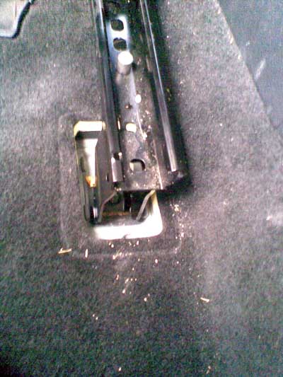
When re-installing the seats please note that you should use new seat bolts and they should be tightened to 50Nm. 1) Removing the seats. The plastic covers over the 4 ends of the seat frame slide off (when prised apart slightly) to reveal the bolts:
When re-installing the seats please note that you should use new seat bolts and they should be tightened to 50Nm. Here is a picture when the left hand seat is removed, exposing the airvents - remove the airvent as-well, its held in by 3 plastic bolts.
2) Removing head unit & glovebox etc. To remove the audio or COMAND unit on the A and B class, you need to gain access to the four torx screws that hold it in place. The procedure is as follows: -
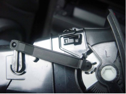
Remove air-vent. This is done using the Mercedes pulling hooks. Close the air-vent (which prevents damage to the mechanism) insert the pulling hooks into the catches which are visible through one of the top slots on each side prising them inwards whilst pulling the vent out. Disconect the connector to the hazard warning switch / airbag-off lamp and then remove the vent completely. Here is a picture of the side of the vent after removing it, you can see the catches - the protruding part holds the unit to the dash board, and is levered inward with the pulling hooks.
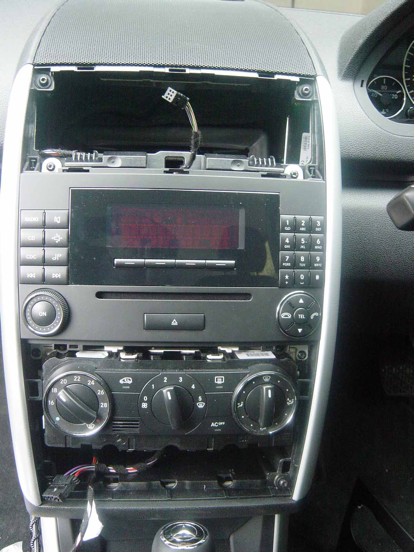
Remove lower panel The lower panel is removed by levering it outwards from the bottom, near the edges using the Mercedes plastic wedge tool (or something else hard that will not damage the panel). I used the pulling hooks after prising the panel forward with the wedge. Once the bottom edge is freed (and quite a lot of force is needed), then the top releases at the sides by pulling sharply. Do not put any pressure against the metal trim at the sides of the central console, they bend or dent easily. Also ensure that pulling hooks are fully inserted as the panel is two pieces and you may split it in two. Once it is all removed, it will look like this, and you can see the 4 torx screws that hold the audio unit in place.
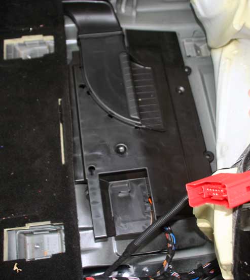
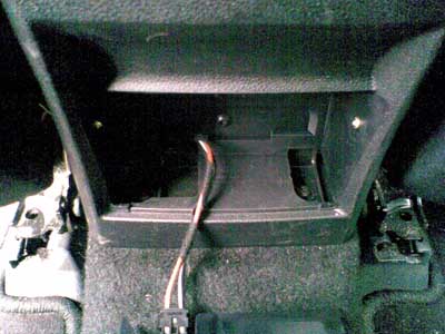
Remove the four screws and the audio unit can be slid out. Note how the wire to the hazard switch is routed, it is clipped into place on the left hand side of the vent hole, and passes through the hole visible in the centre of the picture. Remove the cover above the passenger footwell below the glovebox, there are two TORX scews on the front edge, once removed the cover drops slightly and slides towards you. If you have the interior lights package you will have to unclip the light, or the power to the light as you remove the cover. If you have the CD changer installed, pull the bracket with the CD changer forward from the middle of the glovebox. You will have to reach round and release the power and fibre connectors. The picture below shows those connectors on the back of the CD changer bracket. The power connecor pulls out, the fibre one has a catch which you can see on the yellow dust cover plug on the left.
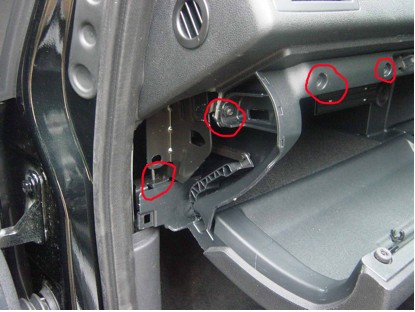
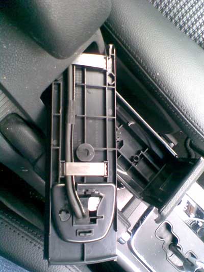
Remove the two TORX screws that hold the bottom of the glovebox that are now visible - you can see the top of part of one of them in the picture below (left most red highlghted area). Open the glovebox and remove the small panel with the airbag sticker on it that is normally hidden by the door. You will probably have to pull off the door frame seal around the area of the panel. Remove the TORX screw for the side of the glovebox (2nd from left in picture below) Remove the covers from the 4 torx screws along the top edge of the glovebox, and the 4 screws. Pull out glovebox, noting the pipework to the airvent for reassembly. Picture of glovebox from side with panel removed, showing some of the screws.
When you re-assemble it, dont forget to put the airvent pipe back correctly connect the footwell light back up.
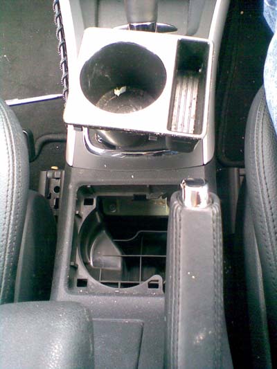
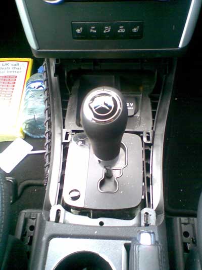
And remove the panel above the driver's feet, and to the left (on left hand drive) or right (on right hand drive) cars. 3) Remove centre console Remove the cupholder by pulling it up - it may require a strong tug if it has not been removed before.
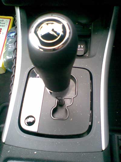
Remove the trim around the gear stick, after putting it in Neutral. Please remember to chock the wheels as its easy to let the handbrake off when removing the centre console. The trim removes by pulling it upward.
Now remove the front trim completely by pulling up fron the back, and when free, sliding the front lip out.
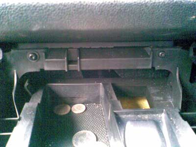
There are two fixing screws at the front edge - remove them.
The 2 rear scews are located under the rear ashtray, which unclips at the top edge and comes out - remove those.
Is the whole lot loose now ?
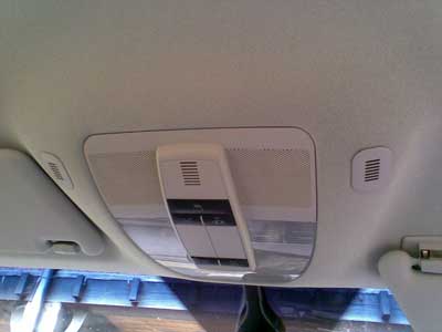
4) Remove OCP The Overhead control panel is removed by inserting two pulling hooks about 2 cm from each rear edge and pulling down - the hooks go in about 2 cm before turning and pulling. Picture of OCP in car with 3 microphone system.
OCP removed
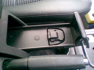
Once the OCP is removed, open it up and install the microphone above the little vent slot at the rear of the unit. 5) TBA xx 6) TBA xx 7) Install UHI connector in armrest Attach the UHI connector into the plate, fix the wires to the plate with the two metal clips, and install it into the drawer in the centre console using the screw which is then covered by the rubber plug.
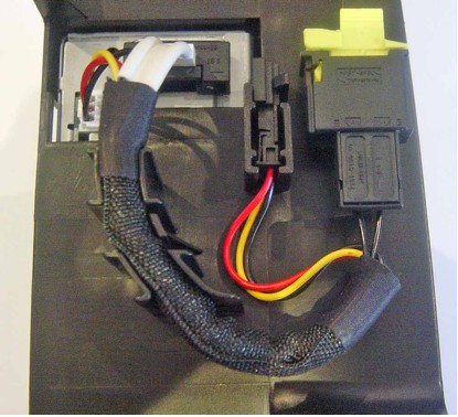
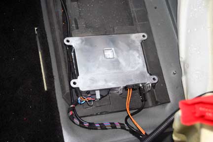
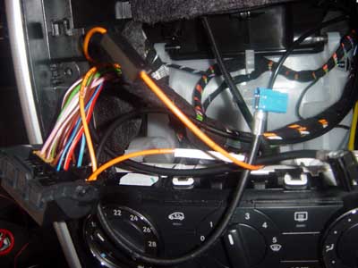
8) Install phone mounting and controller under left hand seat Here is a picture of the controller (with the wiring installed)
Please note that the black antenna wire to the right of the orange cables will not be present with the current looms, and therefore should be ignored. The orange cables are the fibre optic wiring loom. The wires going out of the top of the picture are the control cable and antenna cable going to the centre console UHI connector. 9) Install fibre optic wiring. You can see the fibre optic wiring in the pircture above - it is the two 'orange' cables. It runs from the controller up the left hand side of the car to the head unit. You must be careful with the fibre optics, bending them sharply will break them internally and nothing will then work reliably. If you already have fibre optic wiring in your car, then you will find there is already a pair of orange fibres in the head unit connector - you will have to remove one of them and create a ring. This is done by noting which one of the two fibre is in the corner of the head unit connector, then remove the fibre optic connector from the head unit connector (releasing the plastic lock that holds it in place), and carefully pushing the blue lock pin out. You can then remove the fibre that was in the corner (watch the clips, you need to push them up with a small screwdriver). Insert the fibre optic connector from the phone loom that looks identical to the one you removed into the vacated hole, put the blue lock back it and insert back into the head unit connector., Now join the other two fibres (connectors look slightly different) with a fibre optic connector. Each end of the fibre optic connector is different so you can't get the wrong fibre in the wrong end. Head unit connector picture, with phone wiring inserted into loop using special fibre optic splice. The phone wiring is the fibre at one corner, and the one going into the end of the splice that is furthest away in this picture.
If not, just plug it into the head unit connector, as per the above picture, in the outer fibre optic connector location of the head unit connector. 10) Install copper wiring. Firstly, disconnect the ground lead on the battery, and tuck it out of the way where it can not possibly contact the battery ground terminal again. You can see how the wiring routes in the picture above, you can see the wiring going into the left sill, and the antenna and UHI plate wiring going to the centre console. The antenna wiring in the loom continues to the rear of the car. You need to plug the short extension lead into the main antenna wiring. If you were installing the compensator it would fit between these two leads. When you look at the loom, there is a bunch of cables with
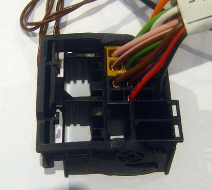
The brown cable goes to the earth point to the side of the front left passenger (driver)'s feet. The two power cables go to the fusebox - each fuse has an 'A' and 'B' slot on the 'fused' side (so 2 devices can be connected). If there is nothing on the live side, then you will need to use the fuse power wiring supplied with the harness to provide power - ensure that all the spare power feeds are plugged in somewhere so they can't short. The Blue/Black most wakeup connectors to the same colour cable on the head-unit connector using splice connector A002 546 74 40. If you do not have one in the head unit connector (because there is no other fibre optic equipment in the car), then you will have to put the connector A013 545 76 26 on the cable and plug it into the head unit connector into the empty hole next to the brown and red cables in the corner of the black centre section of the head unit connector (and roughly in the middle of the connector). The empty cable hole is shown in the picture below: -
When you look at the loom, there is another bunch of cables
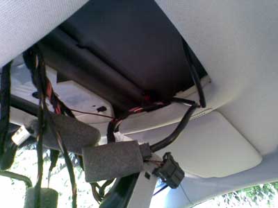
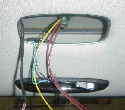
The brown goes to the earth in the left wheel housing in the boot (trunk). The Red/Grey goes back to the fusebox, The 3 pin connector is for the compensator. I have suggested not installing the compensator, but i'd still wire up the power feed and earth. Microphones, if you are installing just one microphone, ground goes to the grey wire and the signal to the purple cable on the 2 pin microphone connector. 11). Drop rear of head liner. Remove the rear centre head liner light by pulling it out using the notch on one side. Then loosen the bolt on the bottom of the antenna and push it out. Do not pull from outside our part of the antenna disconnects and makes it hard to remove. Picture of antenna with AM/FM, GPS and GSM connections, through the light
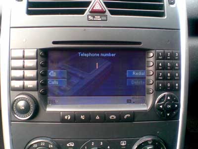
When re-installing tighten the bolt by hand, then a further half a turn. 12) Test and Reassemble. You can check that there is power to the UHI connector by installing a cradle and phone. Unless your car had CDC or Sound system, then COMAND will not find the phone system, so there is no more testing that you can do. If your car has CDC or sound system, then you should be able to make a call from the COMAND system. The steering wheel controls and cluster display will not work until the car has been coded using Star Diagnosis. Coding: The dealer needs to code the car for the phone system to make all the various menus work. Star diagnosis has to be used for this. There are some independants with Star Diagnosis systems that can do this cheaper (probably) then having the dealer do it.
After that is all done, you will be able to access the TEL screen on the COMAND
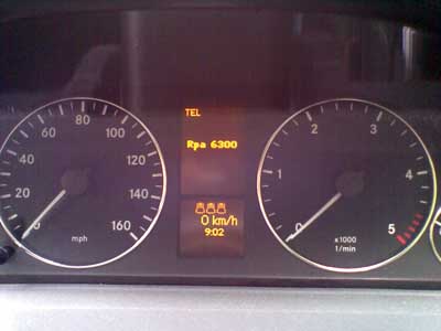
and should have a new menu on the Instrument Cluster to control the phone.
|
If you found this information useful, please support the site by making a donation via Paypal. Any amount at all helps me improve the information on the site. |
Comand Online Ltd - the place to buy Mercedes iPod kits, phone kits, retrofit parts & map disks MY AUTOCAR - THE BEST PLACE TO TALK CARS |