 |
!! Please select country!!
Created: 13 Jun 2009
Last Updated: 22 Sep 2013
|
This article describes how to retrofit the Media Interface (also know as UCI or Universal Communications Interface to the Mercedes W204 C class with the COMAND-APS navigation system. The Mercedes GLK class (also W204), W212 new E class, and W207 new E class coupe use identical parts and all have NTG4 COMAND system and thus these instructions will be suitable for installing in those Mercedes Vehicles also. The interface parts are identical for NTG2.5 and NTG4 systems, so the information here is very relevant to the systems in Model Year 2009 onwards Mercedes A, B, CLK, W211 E, CLS, ML, GL and R class vehicles - which have NTG2.5 COMAND systems in them. Please note that all the photographs are from Right Hand Drive W204 C Class, so if your car is Left Hand Drive, then they are backwards. The GLK, W212 E Class and W207 E Class Coupe are very very similar but dismantle slightly differently. Tools Required Torx TX25 driver Parts Required. You need at least the following part:-
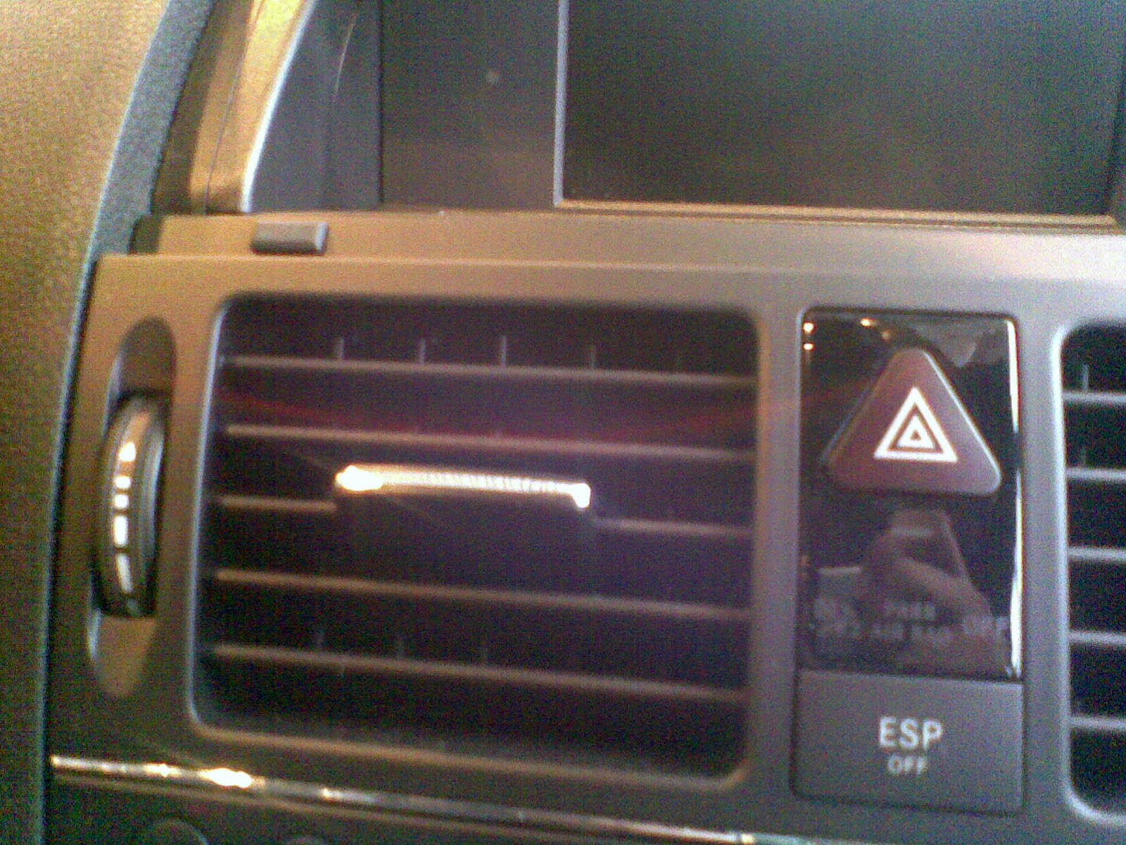
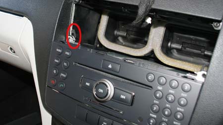
NB. On RHD cars you can make the fibre loom (and avoid the need for the MOST connector) out of 2 x A211 540 31 32. I recommend purchasing the appropriate kit from Comand Online as you see most of the parts are vehicle specific and just the interface is over £300 in UK. You will also need a 'Media Interface' cable set for the vehicle if you are plugging an iPod / USB device or 3.5mm aux device in, or the intermediate cable between the MI connector in the glovebox and the phone cradle if you have an iPhone or iPhone 3G comfort phone cradle and want that iPhone/iPhone 3G to act as the iPod music source for your car. Installation. 1) Firstly remove the COMAND a) Remove air vents This is done by opening the display section -look at where the display section meets the top of the vents, you may have to peel up the front of the display plastic which is stuck to the top of the vents. Then, remove the 2 rubber plugs just above the vents, which act as bump stops for the display and using the mercedes hook tools, slide them in about 3-4 cm and turn them to point downward to catch on the vent (see picture below). The vent can then be pulled out by pulling hard, as it is held in with metal friction catches. Picture of rubber buffer by vent:
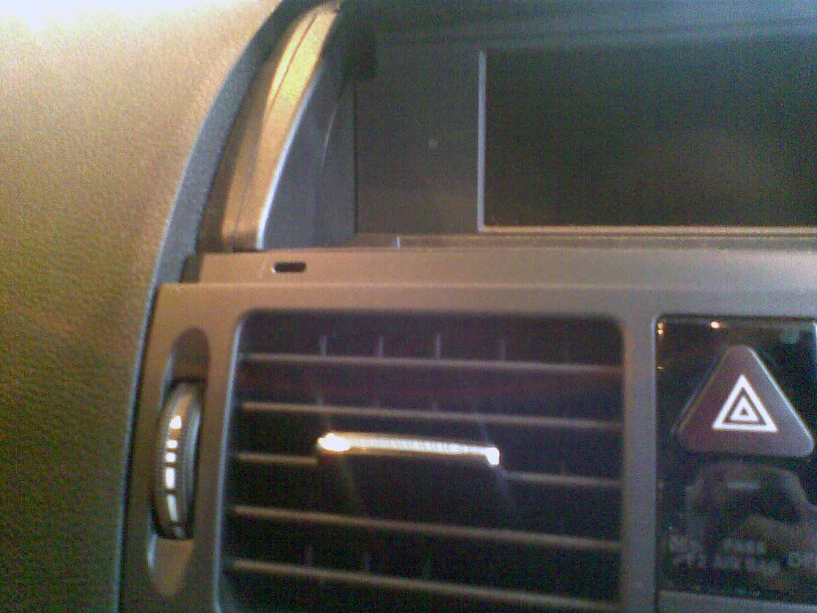
Buffer removed showing hole for extractor hook: -
Picture showing where the pulling hooks actually hook onto the inside of the vent moulding to pull the vent out, and the silver metal friction catch (one on each side) that hold it in place:
Note the positioning of the wiring that goes to the switches in the vent panel, disconnect the wiring, and fully remove the vent. b) Remove radio and lower control panel. At this point you should cover the gear knob with a cloth to protect it from damage from the bottom of the radio unit. Having removed the vents we can see the two torx screws that hold the top of the old radio control unit. Remove these and slide the black latches just behind the screws up, pull out the old radio unit far enough to disconnect the wiring to it and the lower control panel.
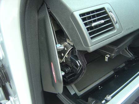
Be very careful of the orange fibre optic cables (if any) in the large multiway connector and the cable to the display - they are fragile and expensive. - Reassembly is the reverse of disassembly - remember to route the wires carefully so they do not get trapped behind the audio unit or the airvent panel. 2) Now Remove the kick panel above passenger feet, and unscrew the one above driver's feet. 3) Now Remove the glovebox a) Pull the passenger door rubber up around the lower part of the hinge end of the door, and unclip the clip holding the side kick panel and remove it. b) Remove the 3 screws holding the panel above the passenger feet up - all of these are at the edge nearest the passenger, and remove that panel. You may have to unplug the wiring from the footwell light if you have one. c) Open the glovebox and pull off the panel at the end of the dash - it hooks in at the edge nearest the door seal so you unclip the edge that is revealed when you open the glovebox Here is a picture of the cover being removed:
Once it has been pulled forward (as in the above picture) it pulls out. d) Look at the AUX socket, using a very small screwdriver clip outward the centre section through the small slots in it, and then it will pull out of the glovebox from the rear. The picture shows the centre section clipped forward.
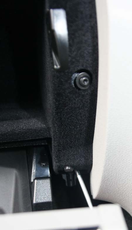
Dont worry if the centre section pops out completely it's easy to re-assemble. e) Remove the screws along the top of the glovebox, the two down the side near the centre console, and the hidden one on the drivers door side. Hidden screw (on door side of glovebox):
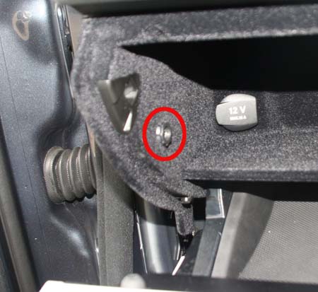
Below is a picture of the two screws on side near centre console - the lower one is awkward to undo and may need a right-angle torx driver - you can see the small torx screwdriver being used in the picture:
f) As you remove the glovebox you will have to remove the connector for the glovebox light, and the cigarette lighter connector. That one removes by pulling at right anges to the cigarette lighter. The picture below shows the cigarette lighter after the connector has been removed. The blue connector on the right of the picture is the glovebox light connector.
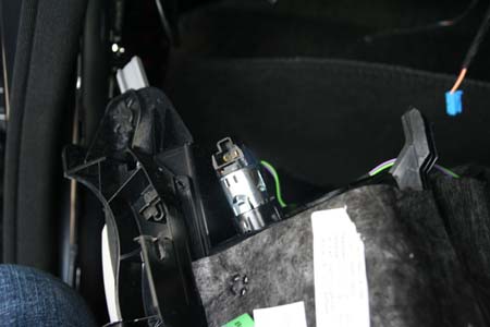
g) If the car has Media Interface you will have to unclip the wiring from the Media Interface itself, and if you wish to remove the glovebox from the car you need to remove COMAND and remove the green fakra connector for the iPod video signal. g) Re-assembly is just the reverse of this. 4) Now Pull down the passenger carpet from the back of the glovebox to reveal a metal plate, unbolt the 3 plastic 10mm bolts that hold it in place to expose the grounding points on the left. 5) Install the MI Loom into the glovebox having removed the knockout section. If your glovebox does not have the knockout then you will need to cut a hole. 6) Install the MI bracket onto the cross member above the glovebox. You can feel the screw holes in the cross member that would hold the bracket to the member but it is only possible to put those screws in before the dashboard is installed. 7) Install the MI interface into the bracket, and cabletie the bracket to the cross member to secure it. Here is a picture of the bracket and interface cabletied in the correct place: -
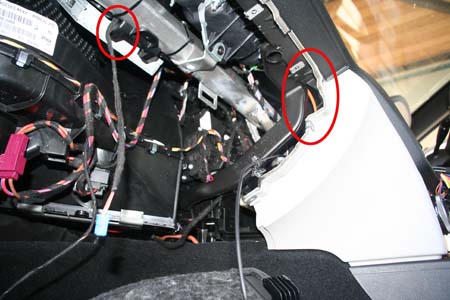
8) If your car has no fibre optic devices (i.e no fibre connection in the multiway connector on COMAND) then you will need to replace one of the connectors on Mercedes original fibre loom with the smaller fibre connector so it will fit in the multiway connector. Remove the blue lock on the fibre connector, look carefully at the arrows on the fibre connector, unclip each fibre from the shell (by bending the lock slightly upward) and move into the correct location on the new fibre connector - put the blue lock(s) back in afterwards. 9) Install the fibre, plugging it into the media interface and routing it to behind the COMAND unit following a path where it wont get damaged when you re-assemble everything (i.e keep it up by the cross-member. The picture below shows the fibre routing and where the glovebox light cable pops out from under the Media Interface bracket.
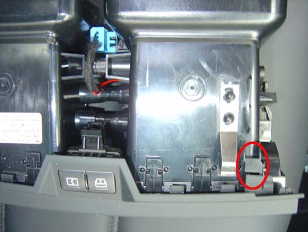
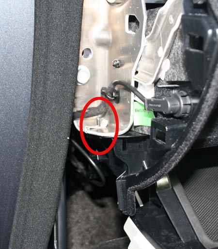
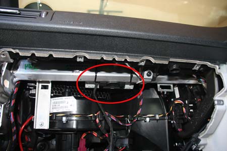
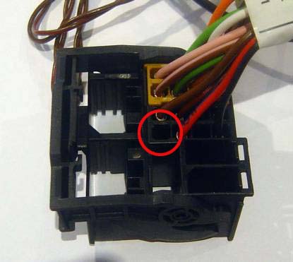
10) if your car has existing fibre in it's multiway connector, unclip that fibre connector from the multiway connector being careful not to break the small latch, remove the small blue lock and remove the fibre going into the connector location with the arrow towards the COMAND unit end of the connector - it is held in place by another plastic tab even though the blue lock has been removed. Take the same fibre from the loom connected to the Media Interface and put it into the original connector and puy that back into the multiway connector. Remove the rest of the fibre connector on the MI fibre loom, and join that fibre to the one you removed from the multiway connector using the MOST joiner. The picture below shows the new MI fibre loom (orange) connected to the pre-existing fibre loom. 11) Plug in the power loom, route the brown wire down to the earthing point revealed in step 4 and connect to the ground point, neatly sticking any excess cable in place using a bit of the felt tape. 12) Route the blue/black cable, the red/white power cable to the back of COMAND, and then route the red/white cable onward to behind the steering wheel. Using the black splice connect the blue/black cable to the one going into multiway connector (see picture in section (10). If you have no cable in that slot you need to put the contact-spring onto the cable and insert it into the multiway connector having released the purple lock at the side of that connector. It goes in the position circled in the picture below: -
13) Route the red/white power cable to the diagnostic socket that is fixed into the kick panel above driver's feet. Cut and solder that to the red/yellow wire on in pin 16 of that socket (yes, it does route to the correct fuse in the fusebox) and insulate. Some people use a splice to do that connection, I prefer soldering. 14) Stick the power cable in place to the inside of dashboard below the steering wheel using strips of felt to ensure it can not get caught anywhere. 15) Re-install the glovebox connecting the MI lead to the Media Interface - the picture in (5) shows the approximate routing. You also have to route the coax lead with green fakra connector to the back of the COMAND unit, it has clips to clip it safely in place. At this stage I only put a couple of screws in to hold the glovebox in place, and put the rest in during final re-assembly. Dont forget to plug the connectors back into the cigarette lighter, glovebox light and re-install the AUX socket. 16) Re-install the COMAND system and make sure it powers on OK. If it powers on and turns straight off again chances are you messed up the fibre loop connections, or the power to the Media Interface controller. Don't forget to plug in the new green fakra which is for video from the MI connector.
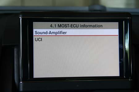
17) ONLY If your car has other fibre optic devices (which at the moment is the Sound System and the DAB tuner), then you can check that the COMAND can see the fibre optic device (which if it cant then the COMAND wouldnt work properly in anycase). This can be done by going into diagnostic mode by pressing Hang-up, then 1, then # keeping all held down together for about 10 seconds, looking in menu 4 (MOST information) and then 4.1 (MOST-ECU Information) where you will see whatever fibre optic components your car had before and a line saying "UCI".
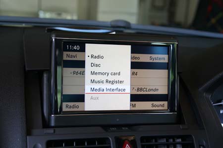
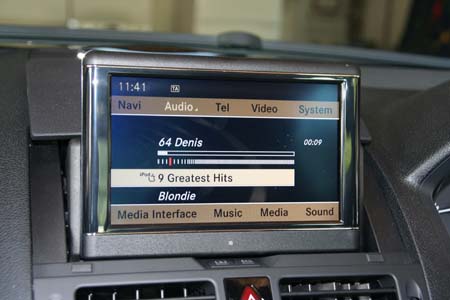
- Please be careful in Engineering mode, you can mess things up badly. 18) Re-install the rest of the glovebox screws, the passenger dashboard kick panel, the side kick panel and the end panel of the dashboard, and put the rubber door seal back into place being careful not to damage the inside of it. 19) The COMAND now has to be coded and the Media Interface controller initialised using a Genuine ONLINE Star Diagnosis machine. There are a few independants with this facility and of course Mercedes Benz authorised dealers have the machines. The workshop needs to have an ONLINE Star Diagnosis machine, and using SDS the workshop needs to tell SDS that option number 518 has been added (which updates the Mercedes Benz central database online) and then SCN code the COMAND system (which downloads the configuration codes from Mercedes Benz) after that update is done (a few minutes). The Star Diagnosis should also be used to initialise the Media Interface (UCI) controller, and check if it needs it's flash upgraded - there have been a number of releases of software for that controller. None of this coding / initialisation / software update can not be done from the hidden engineering mode on COMAND. If the car is pre Model Year 2009, the workshop may have to update the firmware ("flash") the control units using the Telematics update DVD that they will have been sent with their monthly Star Diagnosis disks. 20) Plug in your iPod and enjoy !
Version 1.0 13th June 2009 |
If you found this information useful, please support the site by making a donation via Paypal. Any amount at all helps me improve the information on the site. |
Comand Online Ltd - the place to buy Mercedes iPod kits, phone kits, retrofit parts & map disks MY AUTOCAR - THE BEST PLACE TO TALK CARS |