 |
!! Please select country!!
Created: 30 Nov -0001
Last Updated: 29 Dec 2007
Retrofitting COMAND to Mercedes Benz
Vehicles
24th October 2006 –
Version 1.18 1.18 – Change � info,
add CLK wiring info, fix link 1.17 – Correct/add to
info for AUX input 1.16 – Add CL info,
more Comand part nrs, SL programming note, buying info 1.15 – Add some pre�99
ML info 1.14 – Add detail of
what dealer must do with Star Diagnosis system 1.13 – Some W210
E-Class notes. Another ML-GPS aerial picture. Some other minor tweaks. 1.12 – A long time
since the last update – general additions, pictures, re-arranged to group
vehicle specific information together, added some more COMAND part numbers. 1.11 – more C/CLK
info, also more nav. Sensor angle info. 1.10 – add C/CLK parts
information. CANbus doesn�t need shielded cable. 1.9 – fix part number
for GPS aerial 1.8 – additional part
numbers for COMAND and various extra information 1.7 – fix speed signal
on C2 pin number 1) Introduction
This document describes how
to retrofit COMAND to certain Mercedes Benz vehicles, and how to fit COMAND to
non-Mercedes vehicles. This document relates to the
original COMAND system fitted up until around 2004/2005, where it was replaced
by COMAND-APS. The original COMAND system has CDROM, the later system is DVD
based. The newer system uses completely different technology to the older
COMAND systems. The document is somewhat
lacking in pictures, because when I initially wrote this, I didn�t have a
digital camera, and there weren�t many pictures of COMAND around. This document applies to
European and North American vehicles, and not to Japanese COMAND systems. It is the summary of
information that I know (from playing with COMAND systems for a while), and
information gained from various discussion boards. I don�t warrant that any of
this is correct, and if you damage your car then that is your responsibility.
If you have Teleaid/E-Call, be careful to check that all works once you have
finished. Do this at your own risk. If you do connect things wrongly you could
considerably (and expensively) damage your car. If you are in the US and want
Teleaid to work, you must use US COMAND unit not a European one. Retrofitting COMAND to
Mercedes Benz vehicles (where COMAND was available but was not ordered from the
factory) is not that difficult. It is made considerably easier if the aerial
cabling for the GPS aerial is already present (which it is in the M class and
for many US vehicles, although some extension cables or a splitter may be
needed on some vehicles), or if you are willing to install a separate GPS
aerial rather than the �factory fitted� version on the roof/front-window of the
vehicle. There are two types of
COMAND, with 4 varieties of one of
those types. COMAND
2.5 – the original COMAND unit with a cassette deck used in S and CL, it
is 2.5 din units in size. This was installed until the end of MY2002 COMAND
2.0 – this unit takes 2.0 DIN units (i.e a double DIN slot) – there
are 4 varieties of facia though, and different units have different processing
power and features:- Original: Square
facia as used in ML, original CLK and E classes) 203: Curvey
facia As used in the new CLK/C/G-Wagon 230: As
used in the SL – these have more detailed mapping functions 220: 16x9
Widescreen unit as used in MY2003 S/CL – this is sometimes known as
COMAND MOPF. A ML Class COMAND Unit
(original COMAND 2.0)
A C Class COMAND Unit (203
version of COMAND 2.0)
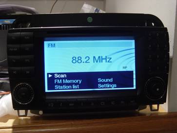
An SL COMAND unit (230
version of COMAND 2.0)
A S/CL COMAND unit (220
version of COMAND 2.0)
This document really only
deals with installing COMAND 2.0 units – i.e. those pictured above. 2) Purchasing a COMAND
unit The cheapest place to
purchase a COMAND unit is from Ebay – there are some useful searches
shown in my buying guide at http://www.mercupgrades.com/buyit.htm You can obtain warrantied
used units from: - COMAND.co.uk
www.comand.co.uk – speak to Mark MBenzNL
www.mbenznl.com - speak to Steve or Wanda Megacomm
www.megacomm.de Audiocomp
www.audiocomp.info If you have a relatively new
car, you should buy the latest available unit for your model. Mercedes part
numbers take the format: - A
XXX YYY ZZ BB The XXX is the vehicle model
number that the part first appeared in. Here is a selection
You should purchase the part
starting with the correct code for your car otherwise the catch mechanism will
be wrong, the gyroscope angle will be wrong, and at a minimum it won�t work
until a MB dealer has re-coded it, and in fact it may not work. This is because
different units expect the Speed, Reverse and Lighting signals to be wired
either via the car�s CAN bus, or via discrete wiring, and cannot easily be
changed. Be ware that if you have one
of the earliest CLK or E (ie model year 1999 and before) then you need to
purchase the exact unit that would have been in the car, or a M class unit
– consult your MB parts department for the part number. The older cars do
not have CAN bus connected to the radio/command (and nor does the M class). Also, if you are installing
in a ML (or a car not designed for COMAND) you must by a ML unit –
although some W208 CLK units can be made to function. I believe that the new
CLK/C/G-Wagen units may be interchangeable, but they will only fit in Mercedes
Benz vehicles as they have non DIN shaped front panels. It may be that the
speed signal is on the A connector on the G-Wagen unit, but they may be able to
be coded to behave like a C/CLK unit. The SL unit is a different shape. Here is an incomplete list
of COMAND unit part numbers – note that this includes COMAND 2.5 systems
for the S/CL (upto MY2002) which have very different wiring to that described
in this document. A more complete list of part
numbers can be found on my website http://www.mercupgrades.com
If you use a European COMAND
unit on a US vehicle then weatherband will not work and AM radio reception will be incomplete because Europe
uses a different spacing between stations than USA. European COMAND units have
a TV button. US units have a blank button instead. The latest US units can be
made to work with TV, older ones can�t. Early COMAND 2.5 units do not support
TV. US units do not support RDS text, European units do. I suspect that having a US
dealer install the latest US software on a European COMAND unit will make
weatherband work again, but lose RDS text. The COMAND unit has an
inbuilt gyroscope, which must be aware of the angle that the unit is mounted in
the dash. On the side of the unit is a special clip – different coloured
clips are used for the different angles – if the wrong one is installed,
navigation may not work well. These are the clips I am aware off: -
These are some of the
differences that occur between different versions of COMAND, although no one
has a public list describing how each is different. a)
Gyroscope angle (see
above table) b)
Software versions
originally supplied c)
Whether CANbus is used d)
Which signals are on
CANbus and which are discretely wired e)
Mounting brackets (how
it fits to the dash board) f)
Whether they can
support DX maps or not. 3) Normal Radio and
COMAND Connectors The standard Mercedes
head-unit�s have various connectors: - A Power
connector B Speaker
connector C Mercedes-benz
special connector (CD power, CANbus etc) D2B D2B fibre optic connector D Antenna
connector F Diverse
Antenna connection (on Audio-30 for instance) COMAND has the following
connectors: - A Power
connector B Speaker
connector D2B D2B fibre optic connector D Main
Antenna connector F Diverse
Antenna connection (small coax connector) E GPS
antenna connector (square grey coax HRS connector) C1 Mercedes
Benz 18-way high density connector (control signals) C2 Mercedes
Benz 8-way high density connector (TV RGB, CD power) Note, if you car has the
Digital BOSE system, connector B will be empty as the amp connects to the head
unit via the D2B fibre optic connection. And, A and B connectors tend
to be moulded together on the car�s wiring. 4) GPS Antenna connector
types There are various connector
types used for the GPS/Phone antenna. On the back of the COMAND
unit is a HRS Connector which is grey in colour.
WICLIC connectors are sometimes
used on the GPS antenna and often on phone antenna.
FAKRA connectors (which are
different colours for different usage) are also used. Blue is used for GPS, Purple for phone. and black for
combined usage.
Mini-UHF connectors are used
for the phone sometimes
See the vehicle specific
sections below for more information on fitting a GPS aerial to your Mercedes. If you do not have a
Mercedes, then Mercedes sell a GPS antenna that can be stuck to the underside
of the dashboard (looking up through the windscreen) and use an extension lead
which converts it to a HRS connector. See the fitting instructions for the SL
later in this document. I believe Clarion also sell
an after market aerial with the HRS connector suitable for COMAND. Be careful with vehicles
with metalised tints on their windscreens, these will not pass GPS signals
through them. I recommend using a roof mount antenna (or the correct antenna for your vehicle if
a factory fit navigation system was available for it). 5) Making up the wiring
converter loom to connect COMAND. As shown above, the radio
connectors are different to those on COMAND in the vehicle. Rather than modifying the
car�s loom, it is better to make (or purchase and modify) a wiring loom
converter harness. Note that for some Mercedes
vehicles (W203/W209/W164 (New C/ New CLK/ ML) there is an adapter loom
available from Mercedes, or the original COMAND loom can be purchased cheaply.
See the vehicle specific install section below. It may be possible to purchase
a pre-made converter loom from http://www.comand.co.uk
, www.megacomm.de or www.audiocomp.info Wiring converter. You need to make a cable up
that goes from the C connector on the vehicles wiring harness to the C1 and C2
connectors on COMAND. I suggest that you start
with the new C (203) / new CLK (209) loom (correct version for whether your car
is left or right-hand-drive), and install that alongside the existing loom. The
D2B wakeup (blue/black) interconnect will be in one of the wiring ducts by the
front door sill (normally found by removing the door sill), and the CAN
distributor in the same duct but in the foot-well. If you have a CD Changer in
the trunk/boot, you will have some splicing to do as the CD power lead only
reaches the glove-box. If not, put your CD changer in the glove-box. Alternatively, purchase the
ML adapter and add the wiring for the reversing signal and the speed signal to
it, or purchase the C/CLK loom and obtain the C connector (Male) to plug into
the existing C connector – note that the C connector (male) may be hard
to obtain. Buying the loom is a
slightly more expensive way of doing this then purchasing the individual
components and assembling it yourself, but the C connector (male) is often not
available. If you start with the ML adapter, you will just need some pins,
connector contacts and twisted pair cable. These are the parts you need
if you are not installing the C/CLK loom : -
You have to make the
following connections :-
A = These two cables must be
twisted pair (to prevent signal interference). If these are the wrong way
round, all sort of electrical things may misbehave. It has been reported that
some cars are wired the other way round, so it may be worth comparing the cable
colours. Note, the colours shown
above are those found in the C (203) class. On CLK (208) (for instance) CANbus
high is black/white and CANbus low is Black, sometimes CD+ is black. You may also want to add the
following wiring when making the loom. These are useful when using a COMAND
system that was not the correct one for your vehicle or if making a loom to use
in the ML
5.1) Diagnostic
Connection In order for the dealer to
configure the COMAND system the head-unit must connect to diagnostic connector. Older European vehicles (pre
2001/2002, except ML, A and new C class) have a large diagnostic connector
under a circular cover in the left or right fusebox under the bonnet. Newer cars have only a 16pin
OBDII connector somewhere on the panel above the driver�s legs (beneath the
steering wheel) – it has a cover on it, and is approximately 2 inches by
one inch. Note that there are some
W210 (E) and W208 (CLK) cars that have both connectors. I Nothing has to be done if
you only have the OBDII connector as a cable is already connected between the
COMAND and pin 12 or 13 of this connector, however with the older connector a
connection must be made between pin 2 of the A connector at the COMAND unit and
pin 34 of the diagnostic connector. If your car had a standard
radio, then the cable will already go from pin 2 of the A connector to pin 33
of the diagnostic connector – it is likely to be coloured grey. The
diagnostic connector comes apart and the pin-insert can be easily moved from 33
to pin 34. Be careful as some of
the connections have power when the ignition is off. If your car had the older
APS system (with separate navigation unit), then you will have to run a new
wire from pin 2 of the A connector to pin 34. Part numbers are :- Diagnostic
connector contact (for pin 34) A
003 545 48 26 A/B/C connector (car side) contact A
011 545 80 26 5.2) Auxiliary Input COMAND can have an Auxiliary
audio input – this is normally found in the glovebox and can be used to
connect a cassette/mp3/md player or other music source. The input connections are on
the C2 connector and are as follows: - Right
Signal 4 Right
Ground 5 Left
Signal 13 Left
Ground 14 Shielded 3-core cable should
be used with the shield connected to pin 14 of connector C2. There is a loom available
from Mercedes for this which has a 3.5mm jack for the glovebox and a white connector that plugs into the
COMAND wiring loom – this is part number A210
440 50 05 It has the 3.5mm jack socket
at one end, and a white four pin connector at the other. You can either cut
that connector off and connect it directly to the C2 connection to COMAND, or
you can make a short loom between C2 and that using the male connector, which
is part number: - A037
545 06 28 Pins for that are A035
545 73 28 If you started using the
C/CLK loom, then you will not need the male connector as it is part of that
loom already. 6) Vehicle Specific Notes 6.1) W163 ML COMAND Mounting. You should also install the
rear support bracket for COMAND. It is part number A
163 546 16 43 GPS Aerial On ML vehicles, a combined
GPS and GSM antenna is fitted on the roof at the back of the vehicle. These
have changed depending on the vehicle�s Model Year of construction. The model
year can be found on a black sticker by one of the front door hinges. Look for
the 3 digit code starting with 80X.
MY1998 is 808, MY1999 is 809, MY2000 is 800, MY2001 is 801, MY2002 is
802, MY2003 is 803 and mY2004 is 804. GPS Aerial - MY2002 to
MY2004 There are separate coax
cables already installed from the aerial (Blue FAKRA) to the back of the head
unit for GPS (wiclic), and from the aerial (Purple FAKRA) to under the
right-hand seat (wiclic or Purple FAKRA), and from the under the seat to behind
the COMAND unit (Mini-UHF or Purple FAKRA) for the phone on European models,
and from the aerial (Purple FAKRA)
to directly behind the head unit on US models.. Some MY2003 vehicles seem to
have an older connector in the hole in the roof, if you follow the cable, you
will find the new type connector for the GSM antenna, and if you go to the left
of the aerial, you will find the blue GPS FAKRA connector. To installing the antenna: -
Open the rear door, and pull off the top-centre trim panel, start at left side,
and pull down gently to release the first clip and work along. You can then
access where the underside of where the antenna fits to install it. Part-Numbers ML
2002-2004 Combined Antenna A163
820 15 75 There are apparently some
MY2003 RHD ML�s that seem to have the correct connectors behind the dash and
under the seat, but only the phone antenna seems to appear in the roof,
connected to an older style aerial connection at the grommet in the middle of
the roof. In fact, the blue GPS FAKRA is somewhere to the left of that, and if
you follow the coax from the aerial connection, you will find the purple FAKRA
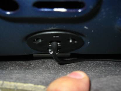
connector for the phone aerial. Here is a picture of the
under-side of �above the head lining� beneath the grommet for the aerial. This
one has the phone cable. You need to remove that connector, and follow the
cable to identify the GSM connection. If you go to the left of the grommet you
will find the blue FAKRA connector for
the GPS.
GPS Aerial - MY2001 and
before On older vehicles there is
only one COAX lead from the antenna to the back of the head unit and a
splitter/amplifier is needed at the head unit end. These come with 2 different
types of connector depending on the model-year This cable plugs into a GPS
splitter/amplifier, and cables go from that to the COMAND and to the phone.
Splitter (FME connectors) A163
820 12 89 Cable from FME splitter to
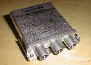
GPS A163 540 01 13 Picture of FAKRA type splitter
Splitter (FAKRA connectors) A163
820 30 89 Cable from FAKRA splitter to
GPS A163
540 09 13 Aerial (GPS and Phone) A163
820 06 75 or A163 820 18 75 (2nd
part replaced 1st part at some point) Wiring Loom. Purchase the wiring adapter
loom from Mercedes, it will save you lots of grief. The wiring loom connects
the reverse signal, and the CD changer power to the COMAND unit. MY2002
Adapter loom A163
540 78 10 MY2001
A163
540 12 09 The MY2001 version is
similar to the MY2002 part, but doesn�t have the GPS aerial converter lead
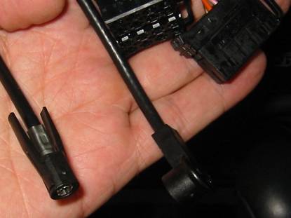
(from WICLIC to HRS), as that is fed direct from the GPS amplifier/splitter. Here is a picture of MY2002
wiring, into which the converter loom plugs.
From left to right, you
have the wiclic for the GSM
aerial, the FM/Am aerial, the A/B connector, and the C connector. The ML does not have an
auxiliary input in the glove box, although it can be added, as described above. Pre Year 2002 MLs. Before MY2001, MLs did not
necessarily have the speed signal on Pin 1 of the A connector, or the
diagnostic connection on Pin 2 of the A connector, and do not have a C
connector with the reverse signal You should look at the A
connector to determine what your vehicle has installed. I believe that MY98/99
have neither connections. To install the diagnostic
connection (so that the COMAND can
be coded using Star Diagnosis by the dealer) – you need to run a cable
from pin 2 of the A connector to pin 12 of the diagnostic (OBDII) connector.
The diagnostic connector is above the drivers feet, and is roughly 2 inches x 1
inch. You will need 2 meters Green
0.5mm cable 1 A012
545 39 26 Diagnostic
connector contact 1 A011
545 80 26 A/B/C
connector contact If you need to install a
speed signal, then please see Wolfgang�s web page http://www.whnet.com/4x4/vss.html
- that will provide speed signal for pin 1, and put the reverse signal on pin 3
– which you should disconnect and then rewire to the COMAND C2 connector
pin 15. You may have to connect the speed signal to C2 pin 6 as-well as A pin
1. Other Units Some CLK units, after MY2001
software update has been done, can be coded to function like ML units, but the
speed signal must be connected to the C2 connector as-well as Connector A Pin
1. 6.2) W208 CLK COMAND Mounting You should install the rear
supporting bracket for COMAND. It is part number RHD
A 208 546 03 43 LHD
A 208 546 04 43 You will have to carefully
cut out the divider between the lower and upper DIN radio slots to allow the
double-DIN size COMAND unit to fit. GPS Aerial The aerial is on the roof,
at the rear. It is a combined GPS and GSM antenna sprayed to match the car. You
should ask your MB dealer for the part number (and colour code) for your car. The GPS aerial cable should
run along the roof lining parallel to the rear windscreen on the right of the
car. (The phone aerial runs along to the left of the car). It then runs down
beside the windscreen, and along the panel to the right of the rear passenger
and in the wiring duct below the right hand door sill, across the front of the
right hand seat and up into the centre console, and then to the COMAND unit. Note, that it may be easiest to run the cable above
the foot-well and into the back of the COMAND, rather than across the front of
the right hand seat – that saves some dismantling of the centre console. If you do not mind about the installation not being
identical to the factory fit, then use the C/CLK (W203/209) class or SL (R230)
class GPS antenna and wiring loom to install the antenna somewhere under the
dash board, looking up through the windscreen. Wiring You may need to add a discrete speed signal to
connector C2 pin 6 – see the W210 E-Class instructions below Other Units Apparently the later 210 units will function in
face-lifted CLKs (i.e. those with steering wheel controls. 6.3) W210 E-Class COMAND Mounting Part of the plastic dash
(under the wood trim) needs to be replaced, its available for a few
euros/pounds from MB dealers – there are pictures at www.megacomm.de explaining how to do this. The plastic part is part
number A210
689 09 16 You will also need a
replacement wood dash surround, as the hole for COMAND is larger than the hole
for the normal radio. Your dealer should be able to work out which part this
needs, as the dash has different cut-outs for different options, there are a
lot of possible part number variations. GPS Aerial There is a combined GPS and
GSM aerial on the roof of the vehicle sprayed to the car�s colour. Ask your MB
dealer for the correct part for your vehicle. You will then need an
extension lead to take that down to the COMAND unit – I suspect the GPS
aerial lead from the W203 C-Class will suffice. (see below). If you do not mind about the installation not being
identical to the factory fit, then use the C/CLK (W203/209) class or SL (R230)
class GPS antenna and wiring loom to install the antenna somewhere under the
dash board, looking up through the windscreen. WIring Some (older) E-Classes have
a speed signal connected to Connector A pin 1, and some do not. Some COMAND
units (such as A210 540 54 89 and A210 540 56 89) need the speed signal
connected – i.e. they do not use CANbus to get the speed signal. You therefore will need to
run the speed signal from Connector C2 pin 6 (and potentially Connector A pin
1) and connect it to the speed signal. On a RHD Model Year 2002 E-Class, I
found this in the left hand wiring duct. The duct accessed by pulling the
plastic sill cover up from the left hand front door, and lifting up the cover
of the duct to expose the wiring looms. In there were 3 wires, located near the
front of the door sill, with insulation on the end of them. These were Green,
Green/White and Green/Black. Connect the Green/Black wire to the COMAND. 6.4) W203 C-Class and
W209 CLK COMAND mounting You will need 4 screws to
fasten the COMAND, A001 984 64 29 There is some copies of MB
service information on how to remove the centre section of the dash here http://www.buellwinkle.com/Comand/COMAND
install and removal WIS.pdf GPS Aerial The antenna is at the top of
the rear windscreen. On US vehicles the aerial wiring is all in place and the
connection for COMAND is already behind the radio (along with the diverse FM
antenna for command (small coax connector). The GPS aerial is stuck to
the rear windscreen at the top in the middle. The following parts are
needed (note that the GPS aerial and aerial lead is probably in place on US
vehicles): - GPS
aerial A203
820 09 75 GPS
lead from aerial to front of car A203
540 70 06 Wiring The original wiring loom is
available which includes the auxiliary audio input connector and wiring. It
does not include the GPS cable or the reversing signal, so should not be used
on the ML. New
C/CLK Adapter loom RHD A203
540 10 09 New
C/CLK Adapter loom LHD A203
540 09 09 The new loom has the C1/C2
connectors for COMAND, the power connector for the CD player in the glovebox at
one end, and connectors to plug in the Auxiliary audio input, the CAN bus
distributor and the �D2B� wakeup distributor (which connects to the other
components such as phone/bose-amp/voice-recognition). I would remove the existing
wiring loom for the �C� connector, and lay in the new harness at the same time,
that way you can follow the wiring back to the CAN distributor and the D2B
wakeup distributor, which I believe are in the sills. The CAN wires are
brown/brown-red and the D2B wires are black/blue. The AUX connector is white,
and you will also need to purchase the small loom described in the �Auxiliary
Input� section below. 6.5) R230 SL-Class COMAND Mounting You will need 4 screws to
fasten the COMAND, A001 984 64 29 GPS Aerial GPS Aerial, sticks to
windscreen behind mirror, part A230 820 08 75 or A001 920 76 75 You will also need the GPS
antenna harness to connect the aerial down to the COMAND unit. A230
540 38 07 Wiring The adapter loom will
function fine, but if, for some reason, you want to install the original wiring
loom, it is COMAND
(Europe) A230
540 50 09 (From chassis F071048) COMAND A230
540 34 07 (Not Japan. MY2002) COMAND A230
540 44 06 (Not Japan, MY03/04) Coding The dealer should also code
the System Diagnosis (or Central Gateway depending on model year) to tell it
that it has COMAND (see section 7). 6.6) W220/C215 S/CL Classs In MY2003 the widescreen
version of COMAND 2.0 was supplied in S/CL class vehicles. This has the same
wiring as the COMAND in other vehicles. Before this date, COMAND units were
very different – they had integrated tape (cassette) player, and very
different wiring – these units were known as COMAND 2.5 (as they were 2.5
din units high). However, the standard fit
system (in Europe) for MY2003 does not support navigation – its seem to
have all the correct connectors, and parts inside, they just seem to have
Navigation disabled, and it can not be turned on with Star Diagnosis. (In fact,
Star Diagnosis warns that that version of COMAND does not have Navigation). I
do not know if the vehicles actually had the GPS aerial installed. As an option (527 in Europe,
530 in USA), a COMAND with Navigation was available See the parts list at the
top of this document and on http://www.mercupgrades.comfor
the MY2003 COMAND units. 7) Dealer Programming Once you�ve installed your
COMAND, it should mainly work – however you really need the dealer to
plug in their Star Diagnosis computer and perform various settings and
configuration. They need to configure the D2B bus to tell COMAND what phones/CD/amplifier
etc is connected. And if you have a phone etc, configure the phone settings as
well. They should also check the COMAND is correctly coded for your vehicle
type, steering and seats (leather/fabric), otherwise lighting may not work, and
navigation may not work because COMAND may not know what speed you are going. If you have a information
display in the instrument cluster, the dealer should program the cluster to
tell it that there is COMAND – then you will be able to view routing
information in that display. Later vehicles (such as the
SL) may also need the �System Diagnosis� control unit and possibly the EIS to
be told that the vehicle has navigation – although I am not sure what is
necessary. Don�t forget that on older
cars you will have had to move the diagnostic connection in the diagnostic
socket under the bonnet, or the Star diagnosis will not find the COMAND system. Many Mercedes dealers are
not used to detailed configuration of COMAND, here is what the dealer must do
(this was done on a W208CLK) a)
Start Star diagnosis, and select the correct vehicle b)
In the Main Groups screen, select �Control Units� c)
In the Control Unit Groups screen, select �Information and Communication� d)
In the �Information and Communication� screen, select �D2B – COMAND or
Audio� e)
In the �Cockpit management and data system� screen, first select �Retrofitting
of D2B Components� -
run through that process and select YES when it asks whether to actually write
the new configuration f)
Return to the screen in (e), and select �Control Unit Adaptations� g)
Select �Read coding and change if necessary� h)
Select �configuration of components (not D2B)� Enable
the following: - Telephone
with enlarged functionality TV
Tuner Instrument
cluster with automatically centering text *** Analog
BOSE (IF YOU HAVE ANALOGUE BOSE only) SMS
transmissions permitted And
save the changes to the COMAND system (***
I think this is true for all models) i)
Return to the (e) screen, and select Radio parameters Set
the �Tuner ident� to the correct country for you (Europe/Japan/North
America/South America) k)
Return to the (e) screen and select �Variant Coding� set
the Model/Series correctly, and the FADER ON if your vehicle has front and rear
speakers (most vehicles except the SL). l)
Return to the menu in (c) above, and select �ICM – Instrument cluster� m)
Select �Control Unit adaptations�, then select �Variant Coding�, then select
�Optional Equipment� n)
Set �Navigation� to �PRESENT� and save the coding. On each of the steps (e),
(h) -> (k) and (n) Star Diagnosis will ask for the coding to be transferred
to the vehicle, which should be done. On the SL (R230) the System
Diagnosis or Central Gateway should also be configured to tell it that COMAND
has been fitted. 8) Installing COMAND in
other vehicles, or I bought the wrong COMAND In order to install the
COMAND in other cars, you need to do the following: - a) Purchase a COMAND system that is �without CAN�, or
one from a ML – I suggest one from an ML, as it tends to have the latest
features. b) Use the wiring description above to supply
power/wakeup to the MB fibre optic CD player if you have one. c) Ensure speed signal from car is connected to
connector A pin 1 AND to pin 6 of the C2 connector. d) Connect reversing signal to connector C2 pin 15 if
you can. e) Connect pin 2 from connector A to car�s OBDII
diagnostic connector pin 13 – if you don�t have a diagnostic connector,
make one up it will need + on pin 16, ground on pin 4 and COMAND on pin 13.
Then the MB dealer will be able to configure the car if he tells COMAND that
it�s in a ML (163) – good luck persuading the dealer to plug his Star
Diagnosis system into a non-Mercedes vehicle. If you already bought the
COMAND and its not one without CAN or from a ML, but is from a CLK (i.e. part
number starting with A208 540 xx xx), then if it has late enough software, it
may be usable: - 1) Have the dealer upgrade the software on the COMAND to
MY01 software using their update disk. 2) Have the dealer �code� the COMAND using Star
Diagnosis to tell it that it is installed in a ML (W163) vehicle. 3) Ensure speed signal is connected to both possible
speed sensor connections as described above. If you purchased an E class
COMAND unit, you will need a CANbus adapter from www.megacomm.de or www.audiocomp.info - This has some
connections for lights/speed-signal/ignition/reverse signal, and a CANbus
output to connect to the CANbus input on COMAND – they come with the C2
connector to make life easy. 9) Further information See my Comand FAQ at http://www.mercupgrades.com/comand/faq.html
for answers to questions that I am regularly asked. See http://www.mercupgrades.com for other
Mercedes retrofits. 10) Help Please take photos of what
you are doing and note any errors in the above, or parts you used on different
vehicles and send them to me, then I can update this document for all to use. I
will try and answer questions sent to me by email (rpa@ibex.co.uk), but I may
be slow. � 2002-2006 Richard
Almeida. All rights reserved Please do not include parts
of this document in your own documents Feel free to reference the document
at my website http://www.mercupgrades.com |
If you found this information useful, please support the site by making a donation via Paypal. Any amount at all helps me improve the information on the site. |
Comand Online Ltd - the place to buy Mercedes iPod kits, phone kits, retrofit parts & map disks MY AUTOCAR - THE BEST PLACE TO TALK CARS |