 |
!! Please select country!!
Created: 30 Nov -0001
Last Updated: 11 Oct 2006
|
Mercedes A/B Class COMAND APS (or Audio-20 CD), CD Changer and Auxiliary input Retrofit. Version 1.3 11 th October 2006 – fix aux wiring harness part number Version 1.2 11th October 2006 – Add Holland coding instruction, fix typo Version 1.1 4th April 2006 – 1 part added Version 1.1 2nd April 2006 – a couple of extra warnings ! Version 1.0 -30th March 2006 – original version Disclaimer. If you want to take a car apart that is your
responsibility. I do not warrant or claim that these instructions are correct,
complete or that your car will not be damaged. You follow these instructions at
your own risk. If you do not feel confident that you can do this, then please
do not attempt it - you can cause
expensive damage! 0) Introduction I ordered my A-Class (W169) without COMAND (APS) or the optional CD changer – UK models come with the Audio-20 CD as standard. I then decided to add COMAND, the CD changer and the AUX input in the glove-box. The AUX input works for both the Audio-20 CD and COMAND. This document describes how I retrofitted all of that. You don�t have to do all of the items, for instance adding 6-CD changer to Audio-20CD systems or just adding the AUX input for the Audio-20CD or COMAND-APS is covered in this document. Adding an Audio-20 CD is pretty much covered in this document as-well. I believe the instructions are identical for the B Class (W245) and the 3 door A-Class, although clearly the inside panel work will be different to my 5 door A-Class. As I am in the UK, my car is right-hand-drive so for left hand drive cars the glove-box is on the other side of the car and some parts are different – but this is shown in the table below. My car was built in February 2006. This 6 CD changer and AUX input cannot be added to a Audio-5 CD 1) Parts needed The parts list below is the same for both A class and B class vehicles. I show UK retail prices (March 2006), however, it is almost certainly significantly cheaper to order any expensive items from a German MB dealer. Look on http://www.mercupgrades.com at the buying recommendations document – it will save you money over purchasing items from a UK MB dealer. There is also lists of part numbers for COMAND-APS and COMAND-APS manuals there. Part numbers starting with B6 are normally specially discounted versions of an equivalent part starting with A (either the same part is supplied, or the same part with a sticker over the A part number is supplied) – just occasionally part numbers starting with A are cheaper than the B part number. For instance, the CD changer as a B part number is about �333, as an A169 part number it is �540. 1a) CD changer install parts
1b) COMAND-APS and Aux input parts. If you want to add the AUX input in the glovebox A169 540 49 08 AUX
input cable (UK List �16.16) If you want to install COMAND B6 782 3558 COMAND-APS (or
A169 820 51 89, A169 820 39 89) If you want to install COMAND (or Audio-20CD) and do not
have a Audio-20 or Audio 50 already installed A203
540 83 08 Wiring
Loom DIN connector -> Multi-way connector If you want to install the GPS aerial on the roof, (i.e. in
the correct place) A169 820 20 75 Combined GPS/GSM/FM antenna base A169 540 59 06 GPS
aerial extension cable Or, above the cluster under the dash A203 820 09 75 GPS
Antenna B6 782 3533 Adapter
cable (or A211 820 00 88) 1c) Useful Tools The following tools are needed or very useful Posi-drive screwdriver 10mm spanner Torx T15 (for CD changer screws and glovebox screws) Long Wedge (for unclipping things), MB part nr W115 589 03 59 00 Dash pulling hooks (for removing vent), MB part nr W140 589 02 33 00 Picture of pulling hooks (2 needed) and long wedge
2) Installation Instructions a) Remove the glovebox This is done as follows Remove the cover above the foot-well below glove box - this is done by removing the 2 screws on the edge near the glove box – if you have the interior lights package you will need to disconnect it�s wires as you remove the panel. - The cover then slides towards rear of car and out Unclip the side cover of the glovebox (the one with the airbag picture on it) Remove the kick panel to the side of the footwell – there are two clips hidden under the rubber door seal – there may be a screw under the little cover in the middle of the panel itself. Remove the two screws below the glovebox, the four under covers along the top of the glovebox and the one under the side-cover. The picture below shows some of those blots after the side-cover is removed Start to pull out glovebox , so that you can access the connector for the glovebox light/switch then you can disconnect that There may an airduct into the glove box that needs removing Then glovebox can be withdrawn Glove-box partially disassembled: showing 4 of the screws before kick panel is removed: -
b) Remove the radio. This is done as follows: Remove the air-vents above the radio i) close the air outlet using the knurled knob ii) release the catch hooks which are on top left and right of vent through the top slat – this is done by inserting the pulling hook with the hook horizontal and then rotating 90 degrees whilst gently pushing outward on the hooks and pull the pulling-hooks forward. There is a picture of the side of the removed vent below. iii) Pull out centre vent until you can disconnect the hazard light switch connector iv) Then pull out the vent completely Remove the dash panel below the radio i) Using a plastic wedge type tool, lever out the bottom of the panel to release the lower clips – I used the pulling hooks on the lower edge near the corners to pull the bottom of the panel out – do not apply pressure to the side of this panel against the metal side trim, it will bend. ii) Then disconnect all the wiring and remove the panel Removed vent showing left hand side clip: -
Once the vent and lower panel is removed it will then look like this: -
c) Install AUX wiring loom The Aux input cable looks like this :-
The white plug clips into the connector which plugs into the
back of the head unit (see picture in next section) – there is only one
place it will fit, and the black end fixes in the glovebox above the air vent.
On the rear of the glovebox is a dimple to show you where to drill a 19mm hole
– the black connector then clips into the hole. You should cable tie the loom to the existing car�s wiring,
all the way to the side of the
car, then there will be enough spare to remove the gearbox easily. Glovebox Dimple for drilling :-
d) Now retrofit the power loom. The power loom has 3 wires - Red/White +12 to fuse box F50 Brown – Ground – to vehicle earthing point W1 Blue/Black – MOST Wakeup – to wakeup either to Z35/10 (wakeup connection point) or direct to back of Radio if no blue/black cable is present there.
You need to route the brown (ground) wire to one of the earthing chassis points in the car – note. you should find one with less than 4 connectors connected already. Mercedes recommend that the red/white wire is spliced to the red/white wire on the head unit connector using soldered connectinos. If the CD changer had been factory fitted, then it would have been wired to fuse 50 (7.5amp) in the fuse box (under the right hand front mat). However, it is very difficult to get to that fusebox (seat and carpet needs to be removed), and the fuseblock may not be present, and probably doesn�t have any power to the live side of fuse 50. So, I used a blue splice connector (Scotch Lock) to connect to the red/white power cable by the head-unit connector. I used the Mercedes smaller black equivalent connector (A002 545 74 40) to connect the D2B wakeup (blue/black) line to the head unit aswell. However, if you have a car without the phone or sound system, then there will be no other MOST units in the car and there will be no blue/black wire in the wakeup pin of the head-unit connector (see picture below – the wakeup pin is the empty hole, in the middle of the connector next to the red and below the brown wires. In that case trim the blue/black lead to length and affix connector A013 545 76 26 to it carefully and insert it into the connector housing. To do this you first have to extract the purple locking bar from the housing – be careful that no other cables fall out when this is removed. Its easiest to push it out from one of the holes where wires can be inserted.
Note that the CD changer will not function with just a power connection – it needs to be connected the head unit via MOST fibre optic connection. e) Install the MOST fibre optic loom The MOST bus is a fibre optic ring, so data goes from one
audio unit (such as CD changer, phone system, digital amplifier) to the next
unit and so on and then back to the starting unit. The fibre optic leads are
orange colour and will be damaged if they are bent too tightly or man-handled. Be
very careful with not to pinch them, bend them sharply, get them trapped behind
the head-unit etc. You should not touch the ends of the fibre optic cable as
they will get dirty and not function properly. Do not cable tie them as this
will crush them. So that the electronics in each of the units on the MOST bus does not have to be powered up all the time (and thus drain the battery) in addition to the two fibre optic leads (in and out) and the normal power supply (ground and 12v), there is a wakeup signal which any unit uses to wakeup all the other units on the MOST fibre ring. The cables for this are normally blue/black and all unit�s wakeup signals are connected together. Each MOST fibre optic plug has two orange fibres connected (in and out) is marked with in and out arrows. (Into the unit it connects to and out of the unit). The recommended order of components on the MOST ring is as follows Head Unit Sound Amplifier Telephone CD Changer. This picture shows the various bits of a MOST cable – it shows the fibre optic cable from one of the A211 540 31 32 looms removed and inserted into the other A211 540 31 32 needed for this installation.
There is a small catch in the outside body of the connector that holds the smaller body part in. The blue catch has to be unclipped, and then each fibre is held in by another small plastic catch that is part of the body of that connector. On both the connector and the outside body you can see the arrows. You can also see what the fibre optic connector looks like when it is not fitted to the housing. If you did not have any other D2B components (phone and/or sound system), then you can just reassemble the fibre two optic looms into one loom and use that. Do not reinstall the outer body of the connector at the head-unit end – it is not used as it is inserted in the muliway connector that then plugs into the head unit. I had some black corrugated tubing from an old fibreoptic loom which I used to cover the fibres, otherwise wrap them in felt tape (available from MB dealer). Here is a picture of the MOST connector partially inserted into a similar multi-way connector: -
If you have other MOST components in your car then you need to insert the CD player MOST fibres into the vehicles MOST loop. Do that as follows: - i) Remove the MOST connector from the multiway connector. The plastic catch can be seen below the MOST connector in the picture above (with a small slot in it, on the cable edge of the bottom of the connector) ii) Strip back about 10 cm of the fibre tape around the fibre looms, very very carefully – this is so you can separate the fibres. iii) Then remove the fibre from the MOST plug with the arrow going away from the fibre end of the plug (i.e. into the head unit)(the upper one in the picture above) and join that to the fibre that is going into the CD changer using the MOST joiner (i.e. with the arrow into the CD changer). Plug the other fibre into the MOST plug that connects to the head unit and put that back into the multi-way connector. When using the MOST joiner you need to push one fibre into each end until it clicks, and then push down the cover to strongly hold the fibres in place. Note – if you are trying to work out which fibre is which then shine a torch down one end and the other end will light up brightly. This is what the head-unit connector looks like after the extra device has been added to the MOST ring (see the black joiner at the top of the picture), and the AUX (white) plug has been installed. In this picture the black fakra connector is for the FM/AM aeral and the blue one is for GPS. The CD changer power/wakeup cables have not yet been connected.
f) Install COMAND COMAND just plugs in instead of the Audio-20 CD (if you don�t have an Audio-20 / 50 then you will need the adapter cable shown in parts list), however you have to install the GPS antenna. Mercedes suggest covering a retrofit aerial (A203 830 09 75) with extra layers of foam attached to the metal side, and fitting it behind and above the cluster. I preferred to install it as though it was factory fit. Firstly remove the rear interior light, it just clips out from the side with the notch in it, and disconnect the electrical connectors to the antenna – unscrew the bolt and push the old antenna out from inside by pushing on the black plastic clip. DO NOT pull it from outside because the black clip comes off and its hard to get it out. Install the new antenna, tighten up the bolt as far as you can by hand and then turn it a further half turn with a spanner. Here is a picture of the antenna installed, but not yet connected.
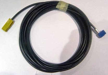
The Yellow cable is the GPS, the purple GSM and the brown the Radio aerials. The black connector is the power for the antenna. The cable at the left of the picture is for the interior light. Then run the GPS antenna cable down the driver�s side of your vehicle, following the existing wiring loom. The instructions below are for a right hand drive car with 4 doors, rather than 2 doors. Note also that officially the cable runs down the left hand side but it is easier to run it down the right hand side as dismantling is slightly easier. The cable looks like this: -
The yellow FAKRA connector plugs into the aerial and the blue one into the COMAND-APS unit. 5cm of this cable should hang from the rear light socket. Firstly remove the white covering around the rear right hand side window, this involves undoing the lower belt fitting for the seatbelt (on the black carpet section of the side of the car) – this should be re-tightened to 32Nm when re-fitting. Then pull of the rear passenger door sill and the seal rubber from there up-to the top of the door. Once the door rubber is removed you will see the catches that hold the white upper panel in, and the clips that hold the black carpet in place also. Below is a picture of the lower top panel (white panel) clip and the upper carpet clip taken from the rear passenger door.
The covering then pulls off and you can then lower the headlining at the rear and run the cable. Here is a picture from the rear showing where the cables come down from the roof lining: -
and a picture from below that: -
Now remove the from door sill (with Mercedes on it) from the front, and the kick panel on the right of the driver (RHD) or passenger (LHD) feet – again there are clips that become visible when the door rubber is removed – and there may be a screw underneath the little cover on that panel. Also remove the panel above the driver (or passenger�s) feet – you will have to disconnect the OBD-II connector (sliding catch), the foot-well light (if present) and the bonnet release. Here is a picture once those panels are removed: -
You can then see the wiring loom going from the front to the back of the car just under the carpet by the sill. I used a cable pulling rod (which is just a long flexible rod), pushed in from the front of the car alongside the wiring to pull the aerial cable from rear to front without having to remove any more panels (or the seat). g) Test it works Now plug everything together to ensure it works. Note that
COMAND will not work until the fibre-optic bus is complete. If you have a multi-meter check that there is power on the
CD changer power lead. Here is a picture of it all connected together. The red
circle shows the position of the earthing point for the CD changer.
h) Assemble CD changer to glovebox If you had CD storage unit that has to be unclipped and not used again Now push the fibre-optic and power plugs through the slot in the glovebox in the bottom corner, re-connect the light, and re-install the glovebox. Next we assemble the CD changer to the bracket Here is the CD changer, new, with the transport bracket held on by sellotape, and with the yellow protection plug for the fibre optic connector.
Remove the transport bracket, and assemble into the glove-box bracket using the four T15 torx screws (A000 990 77 02) Clip the cables into the bracket as shown below: -
And then the CD changer can be installed – which does require a bit of juggling to connect the power and optic cables behind the CD tray before it is fully pushed into the glove compartment. i) More reassembly Now put back all the panel work you removed – once complete it will look like this: -
j) Star Diagnosis If you have replaced the head unit (i.e. installed COMAND or
Audio-20) then I suggest that the dealer runs the �initial startup� sequence
for the AGW (and COMAND) from Star Diagnosis. If you are in The Netherlands and you have just installed
COMAND, the dealer should set the �Navigation Destination entry while driving�
to �NOT Permitted� – this is in the �Navigation� submenu of the �Read coding and change if necessary�
section of the COMAND menus in Star Diagnosis and is to comply with Dutch laws. If you have installed COMAND, the cluster also needs to be
told the car has a navigation system (and thus takes it�s time setting from the
COMAND, and has an extra display for
the map route) – this is somewhat awkward because the cluster is
configured using a SCN code which is entered into Star Diagnosis when
programming the cluster. The SCN code is supplied by Mercedes, which is based
on what options are in the vehicle according to their FDOK central database.
Therefore, you need to have the dealer have FDOK system updated with the new
options you have added – only once that is done can a SCN be generated
that will enable the appropriate menus on the cluster. In the UK, FDOK is
updated by MB UK, in Germany certain dealers have the ability to do that. If you are just adding a CD changer to an existing
Audio-20/COMAND-APS, then the AGW needs to be told about the new component on
the MOST fibre bus, the coding process is very similar to this: - i)
Start Star Diagnosis ii)
Enter vehicle details iii)
Goto �Information and communication� iv)
Goto �Audio, Video, navigation and telematics� v)
Click on �Audio 20� (or AGW, or COMAND depending what you
have) vi)
Click on �Control Unit adaptations� vii)
Click on �Read coding and change if necessary� viii)
Click on �Apply actual configuration of the MOST components� ix)
Check that the actual values show the CD changer and other
components that were in the car (phone/amplifier) and hit F2 and the F4 to
program the configuration x)
Go back up 2 menus and Click on �Retrofitting of MOST
components or IPOD� xi)
Click on �Retrofitting of MOST components� and then hit F2 to
start procedure Note that in step vii/viii you
may have to set up the values in the ring yourself as the �actual�
configuration does not reprsent what is installed. The AGW should be first on
the list and COMAND at the end when selecting what is on the MOST ring, 3) Other information If you find errors or other issues in this document, please
let me know by emailing rpa@ibex.co.uk. If this was useful to you, please go to my website http://www.mercupgrades.com and use (or
bookmark) the links for amazon etc if you use them. There is lots of other useful information there, including
part numbers for COMAND-APS units
and for manuals for COMAND-APS. This document is � 2006 R.P.Almeida. Please do not redistribute or reuse
parts of this document – you may link to the http://www.mercupgrades.com |


If you found this information useful, please support the site by making a donation via Paypal. Any amount at all helps me improve the information on the site. |
Comand Online Ltd - the place to buy Mercedes iPod kits, phone kits, retrofit parts & map disks MY AUTOCAR - THE BEST PLACE TO TALK CARS |